Tuesday, November 29, 2011

Turkey Day Rest

This last week was a much needed break. I unfortunately couldn't make too much progress, but I did get a better start towards coming up with the PCB that will fit over top of the chipKIT. This needs to provide breakout jumpers for all of the panels. Since this is simply going to be headers and a couple of line drivers, it should be relatively simple. the only problem is that this board is going to cost a lot to make, since it has to at least sit over top of the chipKIT. I am designing the board to utilize more boards for expansion later, cutting down on the cost of redesign and reprinting.

I have also made some progress towards completed software. I have updated it with a new stretch of code, and have it compiled down into functions. Everything has compiled and is currently running on the chipKIT already, providing Serial feedback to ensure it's running properly. This Serial data will be removed soon when updated to a more final design in the next few days.

Tuesday, November 22, 2011

Software Progress

The photo on the right will be explained at the end of this post. This is the culmination of a few weeks of struggle in dealing with timers.

In my time struggling and putting off in dealing with the timers, I decided to do some research on anyone else who had dealt with timers. The work that I had dine already did not reveal timers to work with interrupts. The link that I found led to this forum post. The post described someone who was using the capture and compare module, in conjunction with a timer, to invert a pin. I did some testing with the code provided, and it worked just fine. I fine tuned it to respond at a 500 kHz frequency, as seen in the bottom left corner of the display.

Now, the reason why there is a gap in the cycles is that I wanted to do a test regarding the ability to turn off and on the timer, and have it not affect the other parts. This worked beautifully, as seen in the photo above. What this means is that now I need to edit my code, with this new addition, to run the PWM cycling from the foreground to the background.

Monday, November 14, 2011

Design Changes and Milestones


This week, our class is looking at milestones and how the project is coming along. It appears like our project is a bit behind schedule, but it is nothing too bad yet. Hopefully, the design change suggested by David Strait will help to improve our output of LED squares.
 
The improvements suggested by David offer an improvement for holding together the LEDs in the grid. In the present grid, which simply offers a hole for the LEDs to fit into, the leads are able to rotate, making the design much more of a pain to solder together. His solution is simple, redesign the left row on the soldering guide to offer grooves similar to the bending guide to hold everything down in place. As seen in the photo on the right, our 4x4 grid was cut to a 2x4 grid to help get more people working at the same time. However, the drawings that he offered me for redesign we well laid out and offer up this new idea in return: provide grooves for the LED leads to keep them from rotating around too much, and provide cut holes for open areas so that we can solder the leads together. It was a simple improvement, he  put in a lot of work on this, and the design change is exactly the kind of feedback I want to hear about my designs.


Tuesday, November 8, 2011

More Squares!

PCB minus 3 signals
To the left is the picture of the PCB in it's current state. I used FreeRouter, a plugin in KiCad that will route a PCB for you. I basically wanted this done so that I can move on to other things, so I allowed that to work it's magic. There is, however, 3 signals that still need to be routed. For some odd reason, pin 6 on all of the CD4051's are not coming through from the schematic to the PCB design, so I am still in the process of figuring out exactly what is going on with that. I have some pretty clear routes and there is still some clean up to be done to the board, but it is 95% done.

16 X 8 panel.
There has also been some progress made with the assembly of a panel. As you can see in the photo on the left, we have built a 16x8 panel. We intended to use this as a 16x7 text scroller for a competition at the school, but that never got fully completed. It did give me some insight into how much of a pain it is going to be to connect together all of the powers and grounds on a panel.


Kinect on PC


So I got the Kinect to display and track people on the monitor of a PC. Unfortunately, that wasn't my intent. What I was trying to do was to link the Kinect to my own personal computer. For some reason I was missing the mscvp100.dll file on my laptop, which didn't allow the video to show up. I'm currently working to fix the problem so that I may take my programming wherever, but for now I'll be working at UAT's Robolab.

Monday, October 31, 2011

PCB Work

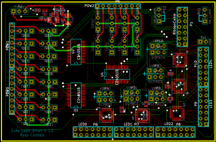
Current state.
 Due to other time commitments, I don't have too much progress to report, but it does have a lot of pretty pictures. This picture on the right shows the current state of the PCB design for a given panel. Below is a full explanation of what all is in each portion of the design.

In addition to progress work on the PCB, it appears like the direct port writing for the software is working just fine. In dealing with software, I need to put some more time into figuring out the timers to correctly change states on the PIC on the chipKIT.


Wednesday, October 26, 2011

Building the Cube

Just like mentioned in the previous post, the construction of the LED cube has commenced. In 2.5 hours, we were able to solder the multi-colored LEDs in an 8 x 8 grid.


By using our bending jigs, we are able to bend the leads on the LED diodes to separate the 3 color channels from the GND (ground). The easiest way we figured for soldering the LED was with the use of a grid that we also printed in 3D as shown on the picture below.

The grid is designed to fit our LEDs with 5/8 in. distance between them. Because the size of our LED panel will be huge, we only fit up to 8 LEDs in our grid mold to easily solder small lines or squares. Once we have enough to build a 4 x 4 grid, we test them to reassure our solder was correct and no leads touch each other. Once tested we built the 8 x 8 grid and tested it again. Thankfully, we had no problems with our first grid. Several students in the Robotics Department have agreed to assist us, but to ensure nice looking, well soldered panels, Ryan and I train the students so each panel will be identical to each other.


We are still soldering the LEDs and will be posting up more pics on its build.

Tuesday, October 25, 2011

Progress!

This last weekend we soldered together a simple little 8 X 8 grid of LEDs. This took 2-3 people, while soldering it together and checking it over, about 2.5 hours to do. This can give us a great baseline for about how long it should take us to assemble the cube. Basically, about half an hour to forty-five minutes per 4 X 4 square, including checking it over for any problem connections. Assuming that we can take the same times to produce the other 8 remaining 8 X 8 cube segments, we could be done with soldering this term's goal of a single panel in about 20 more hours. I feel like the guides printed out helped to smooth assembly along greatly, and ensure that each LED is consistent with every other one.

The above LEDs are set at 5/8" intervals, meaning that also the space between panels will need to be about 5/8". This spacing can give us an estimate that the cube of LEDs, not accounting for any of the controlling wires, will be about 15 inches on a side. Once concern with the smaller spacing is that the PCBs that I am trying to design need to be less than 5/8ths inch tall, or there will be some interference between layers. My biggest concern height-wise is the TIP31As, as these are through-hole transistors. Everything else should be fine at its current height.


Wednesday, October 19, 2011

Initial Troubles

So, I've been trying to program with openFrameworks, but before I was able to compile anything, I am greeted with an error message about missing libraries.
If you are using a Window's computer, make sure when you download Code::Blocks you choose the second download link (codeblocks-10.05mingw-setup.exe). This makes sure you download mingw along with Code::Blocks. For some reason the minimalist development environment was not properly installed on my PC. I found an easy to use installer for those who decided to not get the Code::Blocks installer with mingw.


After properly installing mingw, I was able to write simple C++ codes with no problem.

C++

As mentioned in a previous post, openFrameworks is written in the C++ programming language. Even if you are not fluent in C++, there are several resources online for free. If you follow the setup instructions in openframeworks.cc, you'll find that they recommend installing Code::Blocks.

Code::Blocks is a cross-platform IDE (integrated development environment) that supports GCC and MSVC. User friendly, the software is easy to use and allows development for DirectX, OpenGL, and MATLAB on your Windows, Mac, or Linux PC. You may start playing with openFrameworks by following this link and follow this guide to set up your IDE.

As mentioned before, there are several resources online for C++ tutorials.