Tuesday, December 6, 2011

Reached a max speed?


So, this week's progress has been to update the software. I have gotten the software to a point, as seen in the video above, where it appears like it is running as fast as the software can go. We need to sit down and debug the system more, because clock speed settings and common sense say that we should be running it faster than it currently is doing. It is also a problem if this is running as fast as it can, because from here it can only get slower as we add more processing in the background.

I am presently thinking about moving the serial clocking out to the foreground again, having it update once with the serial buffer, and then using a boolean to track whether or not this data has already been clocked out. This would take lower precedence than incoming serial data, but it should make clocking out faster. I am wondering if, in the future, a faster board may be better, but one step at a time.

Tuesday, November 29, 2011

Turkey Day Rest

This last week was a much needed break. I unfortunately couldn't make too much progress, but I did get a better start towards coming up with the PCB that will fit over top of the chipKIT. This needs to provide breakout jumpers for all of the panels. Since this is simply going to be headers and a couple of line drivers, it should be relatively simple. the only problem is that this board is going to cost a lot to make, since it has to at least sit over top of the chipKIT. I am designing the board to utilize more boards for expansion later, cutting down on the cost of redesign and reprinting.

I have also made some progress towards completed software. I have updated it with a new stretch of code, and have it compiled down into functions. Everything has compiled and is currently running on the chipKIT already, providing Serial feedback to ensure it's running properly. This Serial data will be removed soon when updated to a more final design in the next few days.

Tuesday, November 22, 2011

Software Progress

The photo on the right will be explained at the end of this post. This is the culmination of a few weeks of struggle in dealing with timers.

In my time struggling and putting off in dealing with the timers, I decided to do some research on anyone else who had dealt with timers. The work that I had dine already did not reveal timers to work with interrupts. The link that I found led to this forum post. The post described someone who was using the capture and compare module, in conjunction with a timer, to invert a pin. I did some testing with the code provided, and it worked just fine. I fine tuned it to respond at a 500 kHz frequency, as seen in the bottom left corner of the display.

Now, the reason why there is a gap in the cycles is that I wanted to do a test regarding the ability to turn off and on the timer, and have it not affect the other parts. This worked beautifully, as seen in the photo above. What this means is that now I need to edit my code, with this new addition, to run the PWM cycling from the foreground to the background.

Monday, November 14, 2011

Design Changes and Milestones


This week, our class is looking at milestones and how the project is coming along. It appears like our project is a bit behind schedule, but it is nothing too bad yet. Hopefully, the design change suggested by David Strait will help to improve our output of LED squares.
 
The improvements suggested by David offer an improvement for holding together the LEDs in the grid. In the present grid, which simply offers a hole for the LEDs to fit into, the leads are able to rotate, making the design much more of a pain to solder together. His solution is simple, redesign the left row on the soldering guide to offer grooves similar to the bending guide to hold everything down in place. As seen in the photo on the right, our 4x4 grid was cut to a 2x4 grid to help get more people working at the same time. However, the drawings that he offered me for redesign we well laid out and offer up this new idea in return: provide grooves for the LED leads to keep them from rotating around too much, and provide cut holes for open areas so that we can solder the leads together. It was a simple improvement, he  put in a lot of work on this, and the design change is exactly the kind of feedback I want to hear about my designs.


Tuesday, November 8, 2011

More Squares!

PCB minus 3 signals
To the left is the picture of the PCB in it's current state. I used FreeRouter, a plugin in KiCad that will route a PCB for you. I basically wanted this done so that I can move on to other things, so I allowed that to work it's magic. There is, however, 3 signals that still need to be routed. For some odd reason, pin 6 on all of the CD4051's are not coming through from the schematic to the PCB design, so I am still in the process of figuring out exactly what is going on with that. I have some pretty clear routes and there is still some clean up to be done to the board, but it is 95% done.

16 X 8 panel.
There has also been some progress made with the assembly of a panel. As you can see in the photo on the left, we have built a 16x8 panel. We intended to use this as a 16x7 text scroller for a competition at the school, but that never got fully completed. It did give me some insight into how much of a pain it is going to be to connect together all of the powers and grounds on a panel.


Kinect on PC


So I got the Kinect to display and track people on the monitor of a PC. Unfortunately, that wasn't my intent. What I was trying to do was to link the Kinect to my own personal computer. For some reason I was missing the mscvp100.dll file on my laptop, which didn't allow the video to show up. I'm currently working to fix the problem so that I may take my programming wherever, but for now I'll be working at UAT's Robolab.

Monday, October 31, 2011

PCB Work

Current state.
 Due to other time commitments, I don't have too much progress to report, but it does have a lot of pretty pictures. This picture on the right shows the current state of the PCB design for a given panel. Below is a full explanation of what all is in each portion of the design.

In addition to progress work on the PCB, it appears like the direct port writing for the software is working just fine. In dealing with software, I need to put some more time into figuring out the timers to correctly change states on the PIC on the chipKIT.


Wednesday, October 26, 2011

Building the Cube

Just like mentioned in the previous post, the construction of the LED cube has commenced. In 2.5 hours, we were able to solder the multi-colored LEDs in an 8 x 8 grid.


By using our bending jigs, we are able to bend the leads on the LED diodes to separate the 3 color channels from the GND (ground). The easiest way we figured for soldering the LED was with the use of a grid that we also printed in 3D as shown on the picture below.

The grid is designed to fit our LEDs with 5/8 in. distance between them. Because the size of our LED panel will be huge, we only fit up to 8 LEDs in our grid mold to easily solder small lines or squares. Once we have enough to build a 4 x 4 grid, we test them to reassure our solder was correct and no leads touch each other. Once tested we built the 8 x 8 grid and tested it again. Thankfully, we had no problems with our first grid. Several students in the Robotics Department have agreed to assist us, but to ensure nice looking, well soldered panels, Ryan and I train the students so each panel will be identical to each other.


We are still soldering the LEDs and will be posting up more pics on its build.

Tuesday, October 25, 2011

Progress!

This last weekend we soldered together a simple little 8 X 8 grid of LEDs. This took 2-3 people, while soldering it together and checking it over, about 2.5 hours to do. This can give us a great baseline for about how long it should take us to assemble the cube. Basically, about half an hour to forty-five minutes per 4 X 4 square, including checking it over for any problem connections. Assuming that we can take the same times to produce the other 8 remaining 8 X 8 cube segments, we could be done with soldering this term's goal of a single panel in about 20 more hours. I feel like the guides printed out helped to smooth assembly along greatly, and ensure that each LED is consistent with every other one.

The above LEDs are set at 5/8" intervals, meaning that also the space between panels will need to be about 5/8". This spacing can give us an estimate that the cube of LEDs, not accounting for any of the controlling wires, will be about 15 inches on a side. Once concern with the smaller spacing is that the PCBs that I am trying to design need to be less than 5/8ths inch tall, or there will be some interference between layers. My biggest concern height-wise is the TIP31As, as these are through-hole transistors. Everything else should be fine at its current height.


Wednesday, October 19, 2011

Initial Troubles

So, I've been trying to program with openFrameworks, but before I was able to compile anything, I am greeted with an error message about missing libraries.
If you are using a Window's computer, make sure when you download Code::Blocks you choose the second download link (codeblocks-10.05mingw-setup.exe). This makes sure you download mingw along with Code::Blocks. For some reason the minimalist development environment was not properly installed on my PC. I found an easy to use installer for those who decided to not get the Code::Blocks installer with mingw.


After properly installing mingw, I was able to write simple C++ codes with no problem.

C++

As mentioned in a previous post, openFrameworks is written in the C++ programming language. Even if you are not fluent in C++, there are several resources online for free. If you follow the setup instructions in openframeworks.cc, you'll find that they recommend installing Code::Blocks.

Code::Blocks is a cross-platform IDE (integrated development environment) that supports GCC and MSVC. User friendly, the software is easy to use and allows development for DirectX, OpenGL, and MATLAB on your Windows, Mac, or Linux PC. You may start playing with openFrameworks by following this link and follow this guide to set up your IDE.

As mentioned before, there are several resources online for C++ tutorials.

Monday, October 17, 2011

Cube Project Work

This last week has been overall an interesting week. It started off early on dealing with the bending guide prints. I originally had the bending guide print out at 10 times the size it needed because the export changed my dimensions from millimeters to centimeters. After this save option was found and changed, there were a few more iterations made on the bending guides to refine the size and ensure that the LEDs fit nicely and bend accurately.

After I got the final guide done and the prints, I began to work with the code. I struggled for a day or two with trying to figure why the schematic I had worked out correctly was not operating correctly. I did a lot of digging through the datasheets, and spent a lot of time confused as to why the signals that I thought should be operating at 5V were getting like 3.24 V. I then got an idea, borrowed someone else's chipKIT to confirm the idea, and perused the chipKIT user guides to confirm this idea. It turns out that the chipKIT operates at a 3.3V logic level, and I was expecting a 5V logic level. When providing 5V to Vcc on the TLC5940 PWM drivers, the chip then expects 0.8Vcc, or 4V, to be a high signal. Why this worked in the first video and not now I am still unsure about, but when the logic was changed around to 3.3V as opposed to 5V on Vcc, the chip worked again.

The only other problem that I am having right now, probably because of the way I am running the code right now, the LEDs are visibly flashing. It's obvious that right now the software is still too slow, so my next step with the software, after I finalize the schematics over the next few days, is to implement the interrupts and times so that data is bit banged out and the PWM cycles as fast as I think it can. 

Tuesday, October 11, 2011

Schematics!

This last week I put a lot of effort into finalizing the schematics and ensuring that the board will work the way that we want them to perform. Here's a couple of photos of the full schematics.
Master schematic, which shows connections between the chipKIT and all of the layers.
Full layer schematic.


More details on each of the schematics will follow after the break.


Tuesday, October 4, 2011

openFrameworks

openFrameworks is an open source toolkit designed for "creative coding". Many people, especially artists, use this library to create amazing projects and presentations. A huge community of people hack, explore and share almost everything they produce and discover. Usually written in C++, openFrameworks users make innovative projects by tying other devices.


By using the openFrameworks library, we can use the XBOX Kinect to collect data and export them to our cube. Documents and articles for installing the oF and the Kinect can be found in openframeworks.cc

Since the Kinect can track the skeletal form of a person, why not use that data and project the user inside the cube? Aside from RGB, the Kinect device uses its 2 infrared laser cameras to tell the depth of the image in front of it. This allows us to give the projected skeleton volume and thus more character for the audience to enjoy. By simply adding a second Kinect, we should be able to map both images the Kinect records and merge them so a full 3D object can be projected inside our LED Cube. Point cloud data can be collected from the Kinect, and if we program openFrameworks correctly, we should be able to do something like the following video, but in real life...and with better music.


I already have installed and dabbled with openFrameworks a bit. I would like to begin playing around with a Kinect and my computer, but for now, until I obtain one, I'll continue researching and coding what data can be collected and exported through serial.

LEDs working together!

My progress this week can be summed up in a few photos and a video.


We had gotten our parts in late in the week, so my goal was to begin down the path of software work by getting a couple of TLC's working 10 RGB LEDs. The schematic used is remarkably similar to this schematic found at theArduino Playground for TLC5940's. The only difference now that I will incorporate is that I didn't use the pull-up resistor on the BLANK signal. This now seems remarkably useful, since the chipKIT Max32 seems to write out random data on start-up, and has about a 3 second bootloader before it becomes usable.

This programming did not come along without its share of problems. First off, since I just wanted to get something going, I had to use unsigned ints, as opposed to unsigned 12 bit numbers for storing the RGB values of each pixel. It appears like I will need to overload the assignment operator, something I could not take care of in the short time span that I had.  The software is fairly crude and is actually fairly slow. I was aiming for a proof of concept right now, which was exactly what I managed to achieve.

Monday, September 26, 2011

LED Cube Controller

Aside from building the LED cube, another major attraction is how the cube would be controlled. There has been a few discussions on what interfaces and controls should be used. We are hoping the cube can be usable (and playable) by students and any visitor at UAT. It all came down to 3 possible options.
  1. A Touch Interface
  2. A 3D Joystick
  3. XBOX Kinect Device

Touch Interface
The original plan for the project, a touch interface could be used to track fingers and map the coordinates with the cube. In order to allow full 3D tracking, the cube would require 2 touch screens. Ideally, 1 on the top face of the cube, the other on one of the side faces. The example above shows how an iPhone uses touch screen works. There are 2 conductive screens that are separated by a thin perforated non-conductive layer. When a finger presses the top of the screen, the conductors touch each other through the holes of the middle layer and map X and Y coordinates to the device. Several other touch screens use the same method.

There were some problems with this option due to some factors. Because of the side of the cube, not everyone, mainly kids, would be able to reach all corners of the touch screens. The cube should be accessible to everyone as well as keeping it ergonomic. Another draw back comes from any pending damages. If a screen were to break, it would take some time to replace the screen due to its cost. Another major flaw is the visibility of the cube with the screens attached on the sides. Although transparent touch screen would be used, it would still blur the quality of our presentation. Also, the user would have a difficult time viewing his/her interaction while controlling it.

3D Joystick
The second option for the LED Cube involved the use of a 3D joystick. Whether it be purchased or self made, a joystick provides accurate 3D tracking and control. The benefits of building a 3D joystick from scratch includes using inexpensive materials to build the device, the possibility of including accelerometers and gyro-sensors or potentiometers to the device, and avoiding the costly expense of purchasing an already built product.

It seemed to be the most plausible controller for the cube. A single dot can be moved and tracked within the cube with a 3D joystick. The problem with this controller is simply aesthetics. The project is meant to be artistic and easy to enjoy. Purchasing a joystick, like the one shown above, may be too big and bulky. Placement for the device would be crucial to the enjoyment and visibility of the LED cube. Building a joystick specifically for the cube could fit the aesthetic needs; however, the time developing a 3D joystick may push back the date for the completed finalized project. Other than that, joysticks have been overused and overdone. An awesome project should have a more interesting controller.

XBOX Kinect
In 2010, Microsoft launched the XBOX Kinect device for XBOX 360. They came up with such slogans as, "14 buttons replaced by you" and "You are the controller". The device uses 3 cameras to track movement and depth and use the data collected to allow wireless control of gamers' video games. For its release, the software development kit was released for programmers and game designers to use, prototype, and create games and applications. After the public release of device drivers for Windows, Mac, and Linux, many programmers and engineers have used the Kinect device to make several games and applications for PCs and have robots move or mirror movement.

Having such a device as a controller would be ideal for the LED project.

RGB Cube Update 1


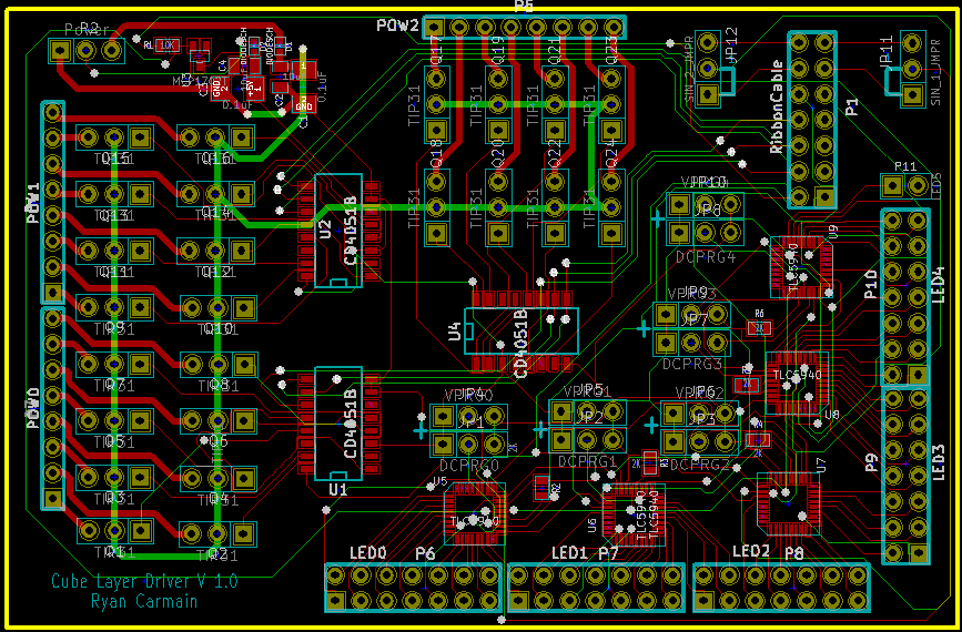
This past week offered up revisions on the schematic design after being looked over by a manufacturing test engineer. Since he had pretty much no part in designing the schematics, he was perfect for a review. He carefully poured over the datasheets, and came up with several changes that have helped improved the schematic design.
1. Pin 3 on the CD4051B (3:8 Demux) was tied to high, so that a pin was freed up on the microcontroller.
2. Vee and Vss were tied to ground, not 5V like I had originally misunderstood.
3. The connection between XERR and gnd was broken.
4. Provided breakout jumpers so that if one still wants to program EEPROM, one can simply change the jumpers for a given PWM driver and program it.
5. Broke up the PWM drivers into 2 circuits. We kept the first 2 on one circuit, and put the last 2.5 on a separate circuit. This took the number of bits that we need to bit-bang per layer from 72 * 12 down to 40 * 12, offering up about a 45% improvement in speed. So now every layer has 2 serial input lines.

One concern we realized is that there is a great risk for fan-out. One microcontroller was going to be trying to drive upwards of 120 chips, while only being able to output 18mA at max. This was going to be a massive problem, one that was solved by providing the 74LS240’s or 241’s on each panel, offering up a buffer to help push that signal to all the panels. I am unsure, as of right now, exactly how to set up the devices between the chipKIT and the layer, but I should have that next week.

We are also looking at providing 2 power supplies. One power supply will be used for just driving the transistors. The other one will be used for all of the logic. We are hoping that providing a high and low pass filter can mean that this cube only needs 1 power supply, and can handle both signals, but the resulting noise may still be too much for the logic chips to handle. Further testing will be required.

I also have some more details about the software. As I mentioned last post, I was going to be using a 3D array of a struct called Pixel. Each Pixel will hold a 12 bit value representing the PWM clock value. Also in the software I will be providing arrays for color balancing. If someone wants to update a color to a certain level, they would set it by saying something like RedBrightnessLevel[12], and now that value at index 12 will be the value stored in the red value at a given pixel. The highest brightness level that we will be providing (with the exception of a possible strobe effect) will be about 70% of the original brightness level, so that it is easier to bear staring at the cube for long periods of time.

After talking with Microchip, their MPLAB X IDE does not yet support the chipKIT, our microprocessor of choice. We will be using the MPIDE, the Arduino and chipKIT compatible IDE modified by Microchip. We will be needing to use direct port writing. Some tests have revealed that MPIDE can toggle a pin at a max of 2.5MHz, which we need significantly faster than that if we are to have any progress made on this. Aside from other requirements, the PWM driver datasheet provided a couple of formulas to calculate minimum frequencies for the PWM clock and the Serial Clock. These formulas have revealed that the PWM clock needs to oscillate at a minimum of 245.76kHz, and that the Serial Clock needs to oscillate at a minimum of 28.95kHz. The PWM clock will be set to oscillate at 500kHz, and the goal for the Serial Clock will be 30kHz.

We are planning on using interrupts and timers to help regulate these speeds, while still being able to do other functionality, like serial communications. The highest priority interrupt will be the PWM timer, which will toggle a pin on timer overflow. I have not yet determined whether I want to directly control this, or use an output compare module to toggle a pin. The next highest priority interrupt will be updating the serial clock. This interrupt service routine will calculate the next set of values to clock out to the PWM driver if it hasn’t already, output these results, and clock the SCLK line. It will also be used to handle a case when everything has been updated, and it is time to shift to a new row. My goal is to be able to precalculate the next set of values, and then just have the ISR output this. However, the serial lines coming in will take priority over this calculation inside of the main function.

Finally, this week has also produced a bending guide, which will be used to ensure that the LEDs are all bent the same way. When assembling this cube, it will be nice to have consistent LEDs that we can just solder together. See the bottom of this post for some photos of the bending guide. The bending guide offers a tight fit to the LEDs, and ensures that these can only go in one direction. The legs are then bent appropriately. The one lead that goes away from the other leads is the power lead, which gets it above the other leads.

Other than that, no new news has come out of the past week. More updates to come!


Monday, September 19, 2011

24 X 24 X 24 RGB LED Cube

The project to be accomplished this term in Robotics Project is the first layer of a 24 X 24 X 24 RGB LED cube. The design of the cube will use panels of 24 X 24 LEDs, and feature a PCB in the corner. The cube itself will feature a door that will provide access to each of the panels. Each row provides power for the LEDs, while we are going to use PWM chips to provide ground and PWM capabilities. The plan is to use 16 brightness levels, which translates into 4096 different colors per LED.

Each panel will be connected between the layers by 11 data wires, power, and ground. This connection is shown below, in Figure 1.


Figure 1. Layers and connections.

Let’s look into a single layer. One layer is located on one panel from above. Each layer features 3 major parts, the LEDs, the power circuit, and the ground circuit. We plan on using a row/column select format by putting the LEDs in a grid. The LEDs will appear in the small grid pattern shown in Figure 2, except it will be extended 8 times in each direction.


Figure 2. 3 X 3 grid of LEDs.

This grid pattern covers the LEDs, which are common anode in the current situation. Each row of LEDs requires about 1.4 A of power. This will be taken care of on the power side, which will use demuxes to drive a given transistor. This transistor is hooked up to a 5V, 30A line to drive every layer. This schematic is show in Figure 3 below.


Figure 3. Power side schematic.

On the ground side of the panel, each TLC5940 (PWM driver) is a current sink driver. The TLC chip offers resistance on each output channel, set by a resistor on the IREF pin. The ground circuit is laid out in Figure 4.


Figure 4. Ground side schematic.

Software has not yet been worked out. The idea is to use a 3D array of Pixels. Each Pixel holds a 4 bit number for red, green, and blue values representing the brightness levels. These brightness levels will then be translated into a 12 bit value, which will then be bit banged out of the microprocessor into the TLCs.


More details to come!

Monday, September 12, 2011

LEDs

Ryan Carmain and Raul Garcia were discussing on on what levels of brightness they should use for their LED Cube project. Garcia asked several professors from the UAT campus including Professor Vesna Dragojlov and Professor Roy Trouerbach. Professor Trouerbach forwarded an email providing further information on how the combination of lights may affect the audience's perception of color.

"There really are no recommended brightness levels as far as I know
It all depends on how a mix of colors will create certain hues and what our preferences are for the various applications.
Color perception will change, depending on which color will have the highest brightness level.
And with LED lights the situation gets a little more complicated as there are varying LED lights that will have different
effects on how we perceive colors.
See http://donklipstein.com/ledc.html. The article is I believe from 2006."

Friday, September 2, 2011

A Maker Wedding

This post is a little late in coming, but this past March I married a wonderful and patient woman, Beth.  For our wedding we wanted to keep costs low and still make it very personalized, so we did all of the planning and made several custom pieces for our special day.  We planned color schemes, table settings, and the hall layout using InkScape - an open source SVG editor, and Beth made beautiful blue and black ribbon table squares for the centerpieces. I designed 3D printed candle holders, and custom ties for my groomsmen presents.


More details and fancy bits after the break.

Automatic Cat Feeder

It's 4am, and I'm sound asleep dreaming of robots when I'm startled awake by 10 lbs of hungry cat jumping on my face with a pleading "mew".  I get up, feed the cats, and unsuccessfully attempt to resume my slumber.  This scene repeated itself every day for only a couple weeks before I decided I needed an automatic cat feeder to maintain my sanity.

The feeder needed to only handle dry food, be able to ration food quantity so that the cats wouldn't get fat, and it needed to have a lot of storage so that the cats wouldn't starve while my wife and I were traveling.  Similar off-the-shelf feeders cost upwards of $50, and I like a challenge, so I set out to build one myself.

Build details and more pictures after the break.

Hash Murder: Statistical Password Breaking

Joe DeMesy implemented an MPI-based parallel password hashing program as the semester project for my Parallel Programming class this semester.  There have been many parallel password breaking programs implemented before, but what makes Joe's implementation unique is how trial passwords are generated.  In his report, he details how he used statistical analysis of known human passwords (from Sony and Grokker leaks) to prioritize what passwords are attempted.  Using this prioritization, he is able to crack a password much faster than the standard random implementation.

You can find Joe's code here.

Wednesday, August 24, 2011

GO GOL: Game of Life using Go Lang

Iggy Kracji's semester project for my Parallel Programming class (CSC471) was to implement Conway's Game of Life using the Go programming language and the Google App Engine.
The purpose of the class was to design, implement and analyze programs that run on parallel architectures, so his output is not pretty, but functional.


You can check out Iggy's code and analysis, and test it yourself at the App Site.

JunkPOV

For his Embedded Programming (RBT211) project this semester Ryan Carmain built a POV display using junk from around our hardware lab - principally the motor assembly of a Draganflyer (yes, those are propellers):

Video and source code after the break.

Friday, April 22, 2011

Engineering Challenge - Integrate Functionality & Livability


Okay so maybe a few of my posts are going to be influenced by the TEDx talk I went to last night, mostly because my head started exploding with all these ideas because of the talks. So I issue a challenge to all my smarty fellow Robotics students [you can do this too Mueth], and any blog readers out there are more then welcome to join in as well. I want you to take 2 or more things and merge them in such a way to improve both their designs and functionality. To increase there aesthetic pleasure as well massively improve there use. Now at this point you're like WTF Kayla really? Yes, really. Its not hard I promise, I came up with like 3 really awesome ideas while just waiting for my ride to pick me up after the TEDx event. ^^ It was kind of funny seeing me trying to write down and draw them out as quickly as possible before I forgot them. And by the way this challenge is inspired by a Mr. Derren Petrucci who gave an amazing talk and who I think would be a good person for UAT's crazy Robotics division to work with~ *hinthintMuethhinthint*

Growing Plants Everywhere - VermiSoks


Okay so I met the guy who came up with this idea, Miguel Jardine, at a TEDx Scottsdale talk last night. It really is an amazingly out there idea with a lot of potential. Pretty much you can have a self-sustained gardening system and you don't even need water. Hm.... no water, we're in a desert with little to no water... I say UAT should look into using this to take over a small part of that empty lot we own to experiment! No breaking ground or construction needed so it doesn't step on anyone's toes. So you should check it out here.

I mean seriously check out some of the pictures from the stuff Miguel grew during the middle of a summer here. The look so yummy and fresh!

Not only that but the system is simple enough where anyone can be taught how to maintain and set up this system. Pretty much what you see in the picture about is a long tube of Earthworms and coconut husks, the base of the VermiSoks system. You then take the waste produced by restaurants or CAFES [I'm looking at you Cuban Pete's] and the biodegradable stuff gets liquefied and feed into these tubes where they feed the Earthworms and then the Earthworms create this super nutrient rich environment for you to grow on. Kind of awesome huh?